|
| The Electrical Compartments and Components |
|
| Electricity and the MH-47 Chinook. Click-N-Go Here to view a larger version. |
| Number One Power Distribution Panel (PDP) |
|
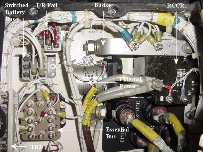
| (CH-47D) Relays and Components contained within the Number One Power Distribution Panel (#1 PDP), upper portion. Shown here are the following relays: Switched Battery Bus, Number One Transformer-Rectifier Fail, Number One Reverse Current Cut-Out (#1 RCCR) , External Power, and Essential Bus. Also included is an example of a typical electrical busbar, and Terminal Board Number Three (TB3). Notice how each wire is either permanently dye marked or paper labeled providing a means of identifying it. Each wire has a unique number assigned to it. thus making it possible to trace the wire as it passes through the various wire bundles, lightening holes, canon plugs, etc., throughout the airframe. Click-N-Go Here to view a larger image. |
|
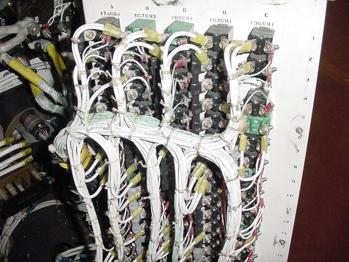
| (CH-47D) Shown here is the front access panel to the Number One PDP opened up revealing what the array of circuit breakers (CB) looks like. By taking a closer look, an observer can spot the manner in which many of the CBs are tied together via small busbars and/or connected to the individual, associated buses. Click-N-Go Here to view a larger image. |
|
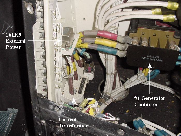
| (CH-47D) Bottom left corner of the Number One PDP showing the Number One Main Generator Forward Current Transformers, the 161K9 External Power Relay, and the Number One Main Generator Contactor. Click-N-Go Here to view a larger image. |
|
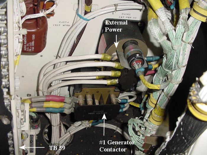
| (CH-47D) Bottom right corner of the Number One PDP, showing the External Power Contactor, the Number One Main Generator Contactor, and TB 59. Click-N-Go Here to view a larger image. |
|
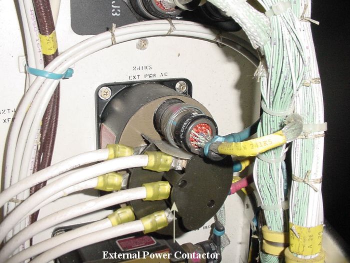
| (CH-47D) Center of the Number One PDP, showing the External Power Contactor. Click-N-Go Here to view a larger image. |
| Number Two Power Distribution Panel (PDP) |
|
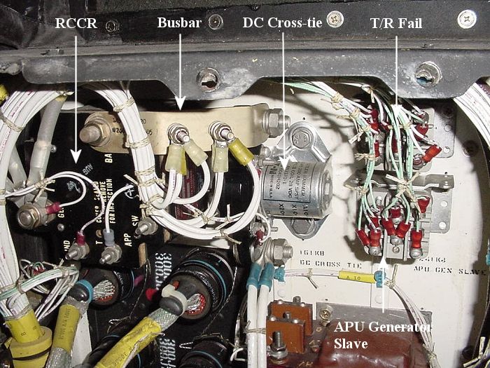
| (CH-47D) Relays and Components contained within the Number Two Power Distribution Panel (#2 PDP), upper portion. Shown here are the following relays: Number Two Reverse Current Cut-Out (#2 RCCR) , DC Crosstie, Number Two Transformer Rectifier Fail, and Auxiliary Power Unit (APU) Generator Slave. Also included is an example of a typical busbar. Click-N-Go Here to view a larger image. |
|
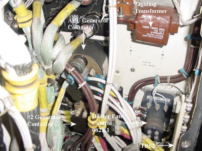
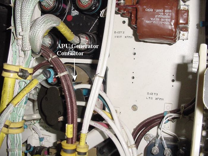
| (CH-47D) Bottom right corner of the Number Two PDP showing the APU Generator Contactor, a Lighting Transformer, the Heater Fan Control Relay (082K1), and the Number Two Main Generator Contactor. Click-N-Go Here to view a larger image. |
|
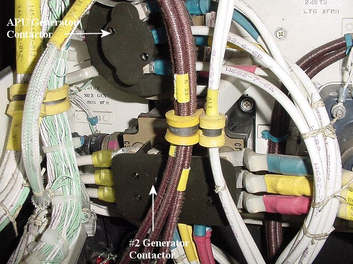
| (CH-47D) Center right side of the Number Two PDP showing the APU Generator Contactor. Click-N-Go Here to view a larger image. |
|
| (CH-47D) Center right side of the Number Two PDP showing the Number Two Main Generator Contactor. Click-N-Go Here to view a larger image. |
|
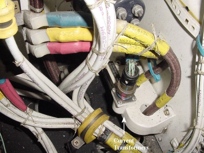
| (CH-47D) Bottom right corner of the Number Two PDP showing the Number Two Main Generator Forward Current Transformers. Click-N-Go Here to view a larger image. |
|
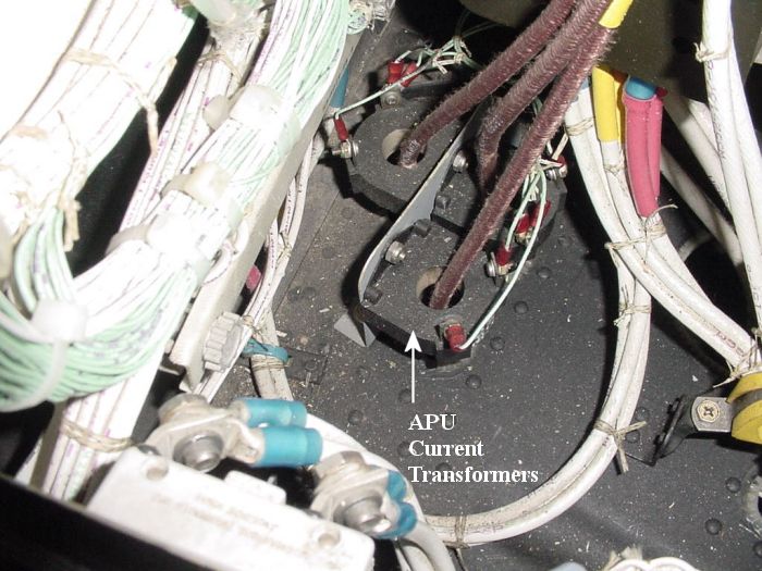
| (CH-47D) Bottom left corner of the Number Two PDP showing the Forward APU Generator Current Transformers. Click-N-Go Here to view a larger image. |
| Want to know how all this works? |
| Download the Student Handout and Powerpoint Slideshow below. Right Click on the link and select "Save Target As" to save the file on your computer. |
| CH-47D Electrical System Operation Student Handout |
| CH-47D Electrical System Operation Slideshow |
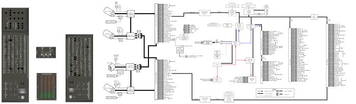
| GA-714A Equipped CH-47D Electrical Chart |
|
| Above, a chart showing the electrical layout of a GA-714A equipped CH-47D Chinook helicopter. Click-N-Go Here for a larger and printable version of the chart. |
| Related Sites |
| Aviator Classes |
 |
|
| Comments or Questions ? |  |
Email the Webmaster. |
|
|