|
| The CH-47 Chinook Engine |
|
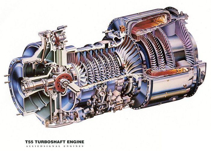
| The Lycoming T55 Engine. This is actually the T55 L-11 Engine and is often utilized to represent the L-712, since they share very similar characteristics. Click-N-Go Here to view a larger image. |
|
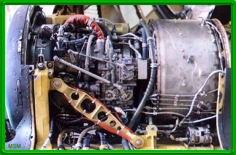
| A Lycoming T55-L712 installed as a number one engine. |
|
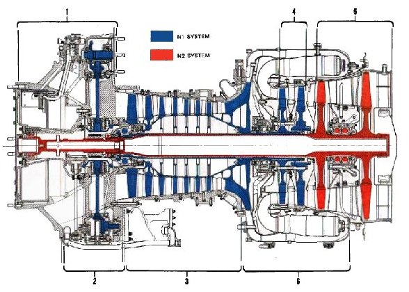
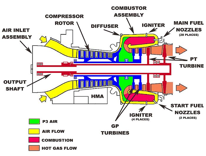
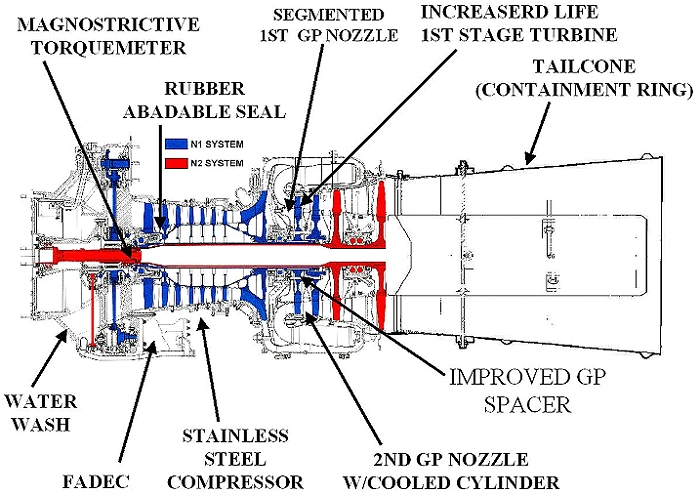
| The internal parts of the L712. |
| As shown in the drawing above, (1) Beginning on the left, air enters the engine past the oil reservoir and (2) flows past the accessory gearbox (AGB), where it then enters seven axial stages and one centrifugal stage of compression (3); the air then exits through a diffuser section into the combustor section (6) where it reverses direction, is mixed with jet fuel, ignited, and again reverses direction to flow across the two N1 (gas producer) turbine wheels (4), and then across the two N2 (power) turbine wheels (5). Finally, the very hot exhaust exits the rear of the engine and is expelled overboard. |
|
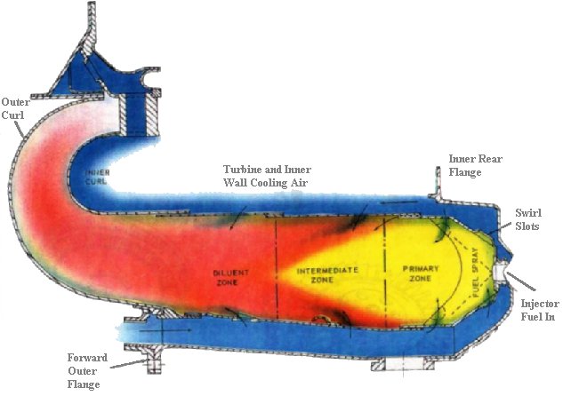
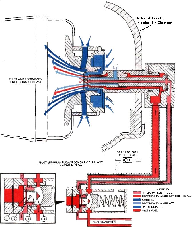
| L712 External Annular Combustion Chamber. |
| The combustion chamber for the L712 engine is a reverse flow, external annular, atomizing type located external to the turbine section. The combustion chamber consists of an annular flame tube. One end of the flame tube is closed by an annular plate which contains 28 swirl cups. Atomized fuel is introduced through 28 dual orifice fuel injectors located in the center of each swirl cup. Louvers in the swirl cups create the mixing vortex into which the fuel is sprayed. The air admission pattern in the primary zone is such that a high degree of fuel-air mixing occurs with this zone. In the dilutent zone of the liner, the hot combustion gases emanating from the primary zone are cooled with P4 air so that the combustion chamber exit profile is compatible with the turbine inlet temperature requirements. Dilution air is introduced through a hole pattern in the forward end of the inner liner assembly. The basic method of protecting the walls of the combustion chamber from the extreme temperatures of combustion (3500 degrees F) is through the use of thin films of air insulating the inner surfaces of the flame exposed areas. These protective layers are introduced through steps parallel to and in the same direction as the flow of burning gases. Approximately 30 percent of the available air is employed for cooling. This cooling film also protects the metal from carbon, fuel residue deposits, and oxidation. The 180 degree turn (left side of drawing above) of gases is accomplished in the deflector assembly passage, which is designed to produce a constantly accelerating flow due to its convergent shape. Hey, it works - trust me... |
|
| L712 Fuel flow from the flow divider to nozzle. |
|
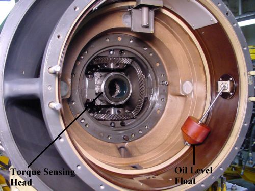
| An internal view of the front of the Lycoming L712 engine. |
| Engine Compressor Stall or Surge |
| A combination of high pressure altitude, high ambient temperature, and dirty or damaged compressors tend to reduce the compressor efficiency - resulting in reduced airflow within the compressor. If these conditions become sufficiently severe, engine surge and/or stall occurs when the airflow over the compressor blades exceeds the critical angle of attack. A sharp rumble or series of loud reports emanating from the engine normally characterizes the onset of compressor surge or stall. These unusual noises are accompanied by abnormal engine vibrations, rapid fluctuations in PTIT, Torque, and N1 for the affected engine, and a noticeable loss of power and RRPM. Avoid maneuvers requiring rapid or maximum power if an engine compressor surge or stall is encountered. Possible aircrew actions include a reduction in airspeed, a reduction thrust below the point of surge or stall, and descent to a lower altitude. Aircrews must avoid conditions of repeated surging\stalling as the attendant transient torsional loads from the engine can cause damage to the engine, drive train, and associated airframe components. |
|
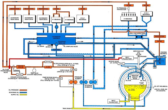
| A diagram of the Honeywell GA-714A Engine Oil Flow. Click-N-Go Here to view a larger image. |
|
| A diagram of the Honeywell GA-714A Engine Air Flow. Click-N-Go Here to view a larger image. |
|
| A diagram of the Honeywell GA-714A Engine Components. |
|
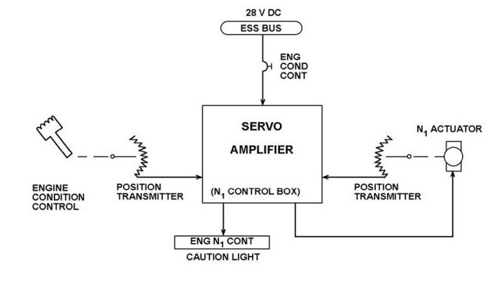
| A Lycoming L712 N1 Engine Control concept diagram. |
|
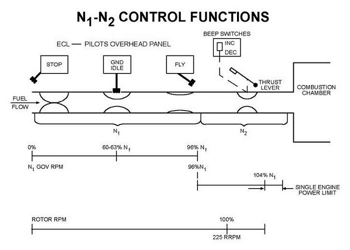
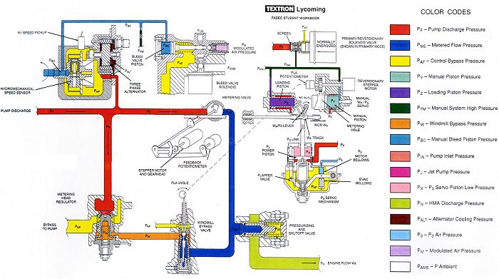
| The Lycoming L712 Engine Fuel Flow Control Diagram. |
|
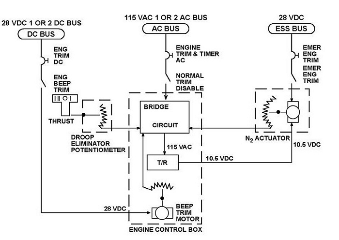
| The Lycoming L712 Engine N2 Control Diagram. |
|
| A diagram of the Honeywell GA-714A Hydro-Mechanical Unit (HMU). Click-N-Go Here to view a larger image. |
|
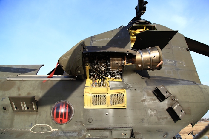
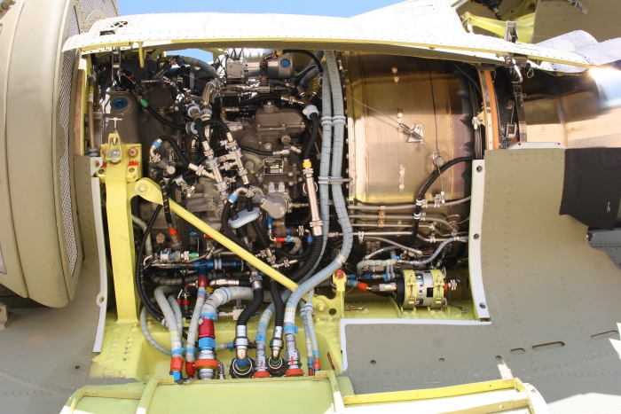
| The Number 1 Engine, a GA-714A, installed on CH-47D Chinook helicopter 88-00089. Click-N-Go Here to view a larger image. |
|
| The Number One Engine installed on CH-47F Chinook helicopter 07-08736. Click-N-Go Here to view a larger image. |
| F.Y.I |
| Did you know? On the GA-714A Engine an "interesting" design feature was incorporated. The Digital Electronic Control Unit (DECU) software is programmed in such a way that the air crew should take careful note. If there is a small air leak in the P3 system the DECU will command the Full Authority Digital Electronic Control Unit (FADEC), a.k.a. the fuel control mounted on the engine, to limit fuel fuel to a certain amount. Depending on what P3 pressure the DECU senses, it will only allow a certain amount of fuel to flow through the engine, regardless of pilot demand. The reduction in fuel flow corresponds to the value of the air leak. This programming will essentially tell the engine to provide no additional power regardless of how much thrust is pulled by the pilot. |
| If the aircraft is operating with both engines running, the point at which the DECU commands the FADEC to limit power will appear as a "low side" engine failure very similar to those sometimes experienced in the days of L-712 and prior engines. When the thrust is lowered below the limit point, engine power will be restored. |
| If both engines experience a P3 air leak, dual engine power available may not be sufficient for sustained flight. The indication will appear as a dual engine low side failure. Rotor RPM will decay when the dual engine demand exceeds power available. The aircraft may have to descend to a lower altitude where the power required is not higher than power available. If that is not possible, the aircraft will be forced to land or crash. |
| If there is a complete failure of P3 system pressure, i.e. a line is completely backed off, then the DECU senses no P3 pressure and defaults to a maximum fuel flow through the engine based on pilot demand (thrust application) with no degradation of available power. |
| There are no cockpit controls, switches or knobs that can correct this situation while in flight. |
| Of interest to note: |
| - Small or minor air leak = restricted power. |
| - Large air leak (a P3 line or component is completely removed, sheared or backed off) = maximum power once again becomes available. |
| See related aircraft - read about the unfortunate loss of MH-47E Chinook helicopter 92-00472 in Afghanistan. |
| Engine Classes |
| Click-N-Go on the links below to download the GA-714 Study Material. It is recommended you "Right Click" and select "Save As" to download the class to your computer. |
| CH-47 AQC Study Materials |
| Click-N-Go Here to download and study the CH-47 Aircraft Qualification Course (AQC) L-712 Student Handout in .pdf format [3.5 Mb]. |
| Click-N-Go Here to download and study the CH-47 Aircraft Qualification Course (AQC) GA-714 Student Handout in .pdf format [8.4 Mb]. |
| Click-N-Go Here to download and study the CH-47 Aircraft Qualification Course (AQC) GA-714 Powerpoint Presentation [62.5 Mb]. |
| CH-47 MTPC Study Materials |
| Click-N-Go Here to download and study the CH-47 Maintenance Test Pilot Course (MTPC) GA-714 Student Handout in Microsoft Word format [43.9 Mb]. |
| Click-N-Go Here to download and study the CH-47 Maintenance Test Pilot Course (MTPC) GA-714 Powerpoint Presentation [57.9 Mb]. |
| Related Sites |
| Engine Diagrams |
| Power Developed by Various Engine Models |
| Boeing Service Bulletin 145-76-1004 (FADEC) |
| Lycoming Engine Development, June 1963 |
 |
|
| Comments or Questions ? |  |
Email the Webmaster. |
|
|