|
| Fuel System Drawings |
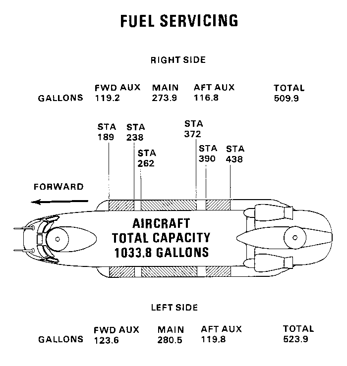
| The CH-47D Chinook helicopter fuel system includes two main tanks, four auxiliary tanks, eight fuel pumps, single point pressure refueling system, and a fuel quantity indicating system. The total fuel capacity is approximately 1028 U.S. gallons. The fuel tanks are mounted in pods on the left and right side. There is a forward and aft auxiliary tank and a main tank on each side. The single point pressure refueling system allows one, all or any combination of tanks to be refueled at the same time. Refueling stops automatically when the tanks are full. The auxiliary tanks feed the main tanks only. The left main tank supplies fuel to the left engine and APU, and the right main tank supplies the right engine and the heater. A crossfeed system allows both engines to be supplied by one tank. A refueling panel is located in the right forward intertank area. It includes a fuel quantity indicator, selector switch, floodlight, power switch, light switch, shutoff valve test switches, power on light, and refuel valve position indicator lights. The pump control switches are located on the overhead panel. The fuel quantity system includes ten probes, two indicators, two selector switches, an inverter, and a switch box. The master caution panel has fuel pressure warning capsules and low fuel warning capsules. The pumps operate on 115 volts AC and are controlled by 28 volts DC. The Fuel Quantity Indicating System operates on 115 volts AC. The low level warning and single point pressure refueling system operate on 28 volts DC. Each tank is ballistic and crash resistant. |
| The CH-47D Chinook helicopter fuel system includes eight fuel boost pumps. Each main tank has two pumps and each auxiliary tank has one pump. The pumps in the auxiliary tanks are mounted in the forward end of each tank. The main pumps are mounted in each end of the main tank. The pumps are single stage impeller type. The motor is rated at 0.30 horsepower @ 10,300 rpm and is thermally protected. The pumps operate on 115 volt three phase AC and are controlled by 28 volts DC. The auxiliary tank pumps have two thermistors mounted on them. The thermistor controls the AC voltage to the pump. When fuel is consumed below the level of the both thermistors the pump will shut off. Two thermistors are used to ensure the tank is empty and prevent the pump from shutting off prematurely because of fuel motion. |
|
| A drawing showing the fuel tanks and capacities as used on the CH-47D Chinook helicopter. Click-N-Go Here to view a larger version of this image. |
| Fuel Control Panel |
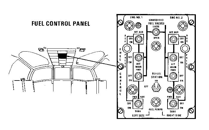
| The fuel control panel is located on the overhead panel in the cockpit. It includes ten switches and two indicator lights. A diagram of the fuel system is drawn on the panel. The fuel boost pump switches are positioned on the diagram at the pump position. The crossfeed valve switch is shown on the diagram connecting the two systems. The refuel station switch supplies 28 volts DC to the refuel station control panel, located in the forward right intertank area, when it is turned on. The two indicator lights are connected to the auxiliary tank pressure switches. If only one auxiliary pump on a side is operating, the indicator light will be on. The main tank pump switches supply 28 volts DC to the relays in the relay control box. The auxiliary pump switches supply 28 volts DC to the dual thermistor control units for the pumps. If the pump thermistors are covered by fuel, the DC voltage will operate the relay in the relay control box. Operating the crossfeed valve switch connects 28 volts DC to the valve motors and positions the valve to the position selected by the switch. |
|
| A drawing showing the location of the Fuel Pump Control Panel in the CH-47D cockpit. Click-N-Go Here to view a larger version of this image. |
| The Main Tanks |
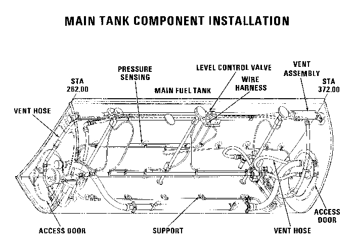
| The internal lining of the fuel bladders contain mounting points for all the equipment that is installed on the inside of the tank. Each tank has a vent system, level sensing equipment, pumps, and equipment for the pressure refueling system. Check valves are installed throughout the fuel system to control and route fuel in the proper direction. |
|
| A drawing showing the components installed inside the main fuel tanks of the CH-47D Chinook helicopter. Click-N-Go Here to view a larger version of this image. |
| The Jet Pump |
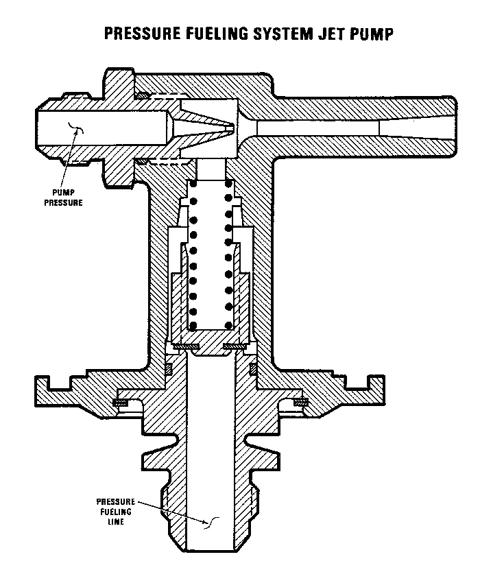
| The jet pump is installed in the left and right main tanks. It is used to remove the fuel from the single point pressure refueling crossover fuel line after the aircraft has been refueled. The forward fuel boost pump of each tank is used to operate the jet pump. |
|
| A drawing showing the Jet Pump located in the left and right main fuel tanks that is used to evacuate the crossover fuel line after single point pressure refueling. Click-N-Go Here to view a larger version of this image. |
| Related Sites |
| Flight Control System |
 |
|
| Comments or Questions ? |  |
Email the Webmaster. |
|
|