|
| The Landing Gear System |
|
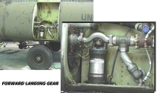
| Forward Landing Gear (right front fuselage) |
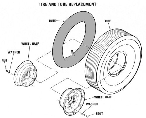
| The landing gear system consists of four non-retractable landing gears mounted on the fuselage pods. The forward landing gears are a fixed cantilever type and have twin wheels. The aft landing gears are of the single wheel, full swivel (360 degree) type, and can be power centered and locked in the trailed position. In addition, the aft right landing gear can be steered from the cockpit by using the steering knob on the console. Each landing gear has an individual air-oil shock strut and is equipped with tube type tires. |
|
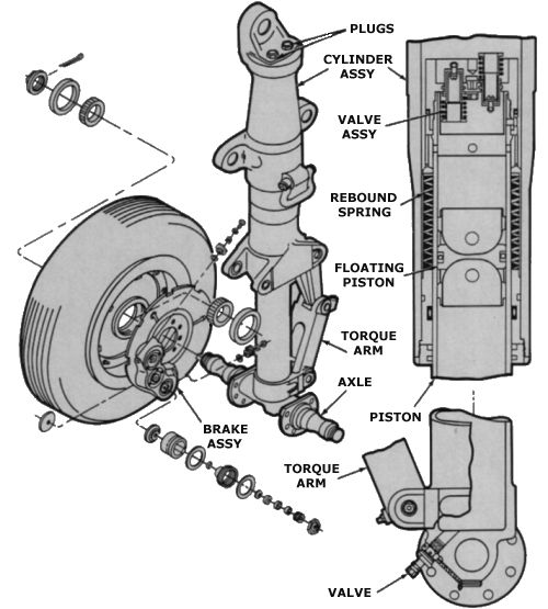
| Component breakdown of the Forward Landing Gear |
|
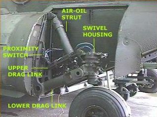
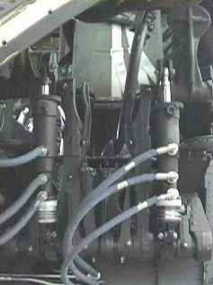
| The Aft Landing Gear |
| Proximity Switches |
|
| Proximity Switches (right rear fuselage) |
| Two proximity switches are installed, one on each aft landing gear. Each switch is activated when its associated shock strut is compressed during touchdown. The switches improve ground handling by reducing pitch axis gain of the Advanced Flight Control System (AFCS), by cancelling the Control Position Transducer (CPT) signal and the longitudinal stick input to Differential Airspeed Hold (DASH) actuators, and by driving both Longitudinal Cyclic Trim (LCT) actuators to the ground position. In addition to the above functions, the switch on the right aft landing gear, when activated, disables the flare dispenser to prevent accidental flare release and enables the hold function of mode 4 transponder codes. |
|
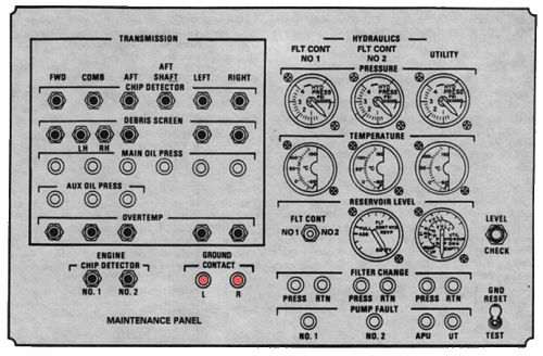
| Maintenance Panel |
| On helicopters equipped with Ground Contact indicating lights, activation of the proximity switches when the associated shock strut is compressed will cause the associated Ground Contact indicating light on the Maintenance Panel to illuminate. |
| Should either or both GROUND CONTACT indicating lights remain illuminated after lift-off to hover, the indicated system(s) DASH will not function properly in forward flight. If both GROUND CONTACT indicating lights remain illuminated after lift-off, the AUTO function of both cyclic trims system will be inoperative and both LCT actuators will remain in the ground position. | |
| Aft landing gear proximity switches are not activated in a water landing. As a result, DASH actuators will respond to longitudinal stick motion, producing an apparent increase in control sensitivity. Cyclic motion of (+/-) 3/4 inch from neutral, if held, will drive the DASH actuators hard over. If longitudinal cyclic movement is required for taxiing, set the AFCS system select switch to OFF. |
| Steering and Swivel Lock System |
|
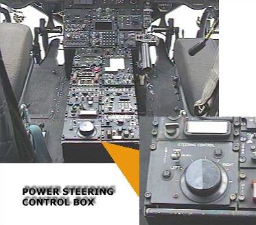
| Cockpit controlled Power Steering |
| The steering and swivel lock system consists of the power steering control box with the STEERING CONTROL panel on the center console, utility system pressure control module, power steering actuator, power steering module, swivel lock module, and the PWR STEER master caution capsule. The STEERING CONTROL panel consists of a three way SWIVEL switch and a steering control knob. The SWIVEL switch controls operation of the power steering and swivel locks. The switch positions are arranged so the power steering system cannot be energized and used with swivel locks engaged. The aft right landing gear is hydraulically steerable and electrically controlled by the steering control knob. |
|
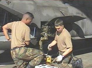
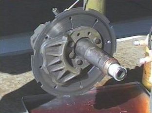
Chinook 85-24339 - SGT Neal Williams and SGT Domingo replace the right aft landing gear after a leak was discovered in the centering cam portion of the swivel housing (28 October 1999). |
|
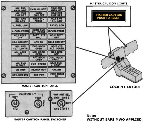
| Master Caution Panel |
| The PWR STEER caution capsule on the master caution panel indicates that power steering circuits have failed or the aft right wheel has exceeded turning limits. These limits are set at 58 degrees for a left turn and 82 degrees for a right turn. If turning limits are exceeded, an out of phase switch on the landing gear automatically closes the power steering solenoid valve, lights the caution capsule, and removes electrical power from the control box. To re-energize the power steering system, the landing gear must be returned within operating limits and the SWIVEL switch must be recycled. |
| Hydraulic power to operate the power steering actuator and the swivel locks is supplied through the utility system pressure control module and a separate power steering and swivel lock module. Electrical power to control the steering and swivel locks system is supplied by the Number 1 Direct Current (DC) bus through the BRAKE STEER circuit breaker on the Number 1 Power Distribution Panel (PDP). |
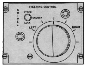
| Steering Control Panel |
|
| Power Steering Control Panel |
| The Steering Control Panel is on the aft end of the center console. It contains the SWIVEL switch, the steering control knob, a fail safe module and relay, and a servo-amplifier. The fail safe module monitors the steering electrical circuits. A malfunction which could cause a steering hard over will be detected by the fail safe module and relay which disables the system and turns on the PWR STEER caution light. |
| The SWIVEL switch is a three position switch labeled STEER, UNLOCK, and LOCK. Setting the switch to STEER applies DC power to the circuits in the power steering control box and arms the power steering actuator. Rotating the steering control knob will activate the power steering actuator and the aft right wheel will swivel. Setting the SWIVEL switch to UNLOCK de-energize the power steering circuits in the control box and the power steering actuator. It maintains the swivel locks in the disengaged position and both aft wheels are free to swivel. Setting the SWIVEL switch to LOCK energizes the swivel lock and centering cam control valve. Utility system pressure is directed to the lock port of the swivel lock cylinder and centering cam. The aft wheels will rotate to neutral trail position and the swivel lock will engage when helicopter weight is lifted from the rear wheels. AFCS heading hold is disabled at STEER and UNLOCK. |
| The steering control knob has index marks around the knob to indicate degrees of knob rotation LEFT or RIGHT in increments of 30 degrees. These index marks do not represent wheel turn angle; they are reference marks only. The knob is spring loaded to zero turn angle. Power steering is accomplished by rotating the knob a given amount in the desired direction. When the knob is rotated, a servo valve on the power steering actuator regulates hydraulic pressure to extend or retract the actuator. A feedback variable resistor, also on the power steering actuator, stops actuator travel when the selected turn radius is reached. |
|
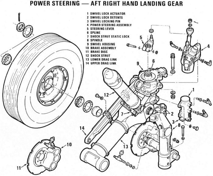
| Power Steering component breakdown |
| Brake System |
|
| Brake Disc |
| The four wheels of the forward landing gear, and two wheels of the aft landing gear, are equipped with self adjusting disk brakes. Both forward and aft brakes can be applied and brake pressure maintained by depressing the pedals. Hydraulic pressure is supplied by the utility hydraulic system. The normal 3000 psi utility system pressure is reduced to 1500 psi by a pressure reducer located on the ramp area adjacent to the Number 1 and 2 aft drive shafts. |
|
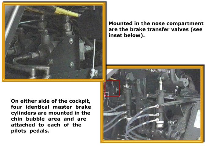
| When either the pilots or copilots brake pedals are pressed, pressure from the master brake cylinders goes to a transfer valve in the brake lines. This allows independent braking by either pilot. From these transfer valves, pressure is directed through a parking brake valve to the forward and aft wheel brakes. |
| Myth |
| Contrary to the beliefs of some, it is NOT necessary to "pump" the brakes in a Chinook. The Chinook is a helicopter, not a car, and the brake systems are entirely different in function. Once one has depressed either brake pedal in a Chinook, approximately 1390 PSI 1 of hydraulic pressure is proportionately applied simultaneously to the calipers of each brake system on the corresponding two landing gear. If one depresses both brake pedals, all four landing gear mounted brake systems get a shot of stop juice. |
|
The left side landing gear wheel brakes operate independently from the right side. Pressing either the pilots or copilots left pedal to depress the left master cylinder will operate the left side wheel brakes. Pressing either right side pedal to depress the right master cylinder will operate the right side wheel brakes. |
| Parking Brake |
| A parking brake handle is at the bottom left corner of the pilot's section of the instrument panel. The brake handle is mechanically connected to the parking brake valve. The parking brake valve is electrically connected to the PARK BRAKE ON caution capsule on the master caution panel. When the brake pedals are pressed and the parking brake handle is pulled OUT, pressure is trapped and maintained on the forward and aft wheel brakes. At the same time, electrical power from the DC essential bus through the LIGHTING CAUTION PNL (Panel) circuit breaker, lights the PARK BRAKE ON caution capsule. |
| The parking brakes must be released by applying pressure to the brake pedals. This action automatically opens the parking brake valve, retracts the parking brake handle, and extinguishes the PARK BRAKE ON caution capsule. |
| Isolation Switch |
| The brakes and steering isolation switch is on the HYD (Hydraulic) control panel on the overhead switch panel. It is labeled BRK (Brake) STEER, ON, and OFF. The switch isolates the brakes and steering hydraulic sub-systems from the rest of the utility hydraulic system in the event of a leak in the sub-system. The normal position of the switch is ON. The switch is guarded to ON. Setting the switch to OFF, closes the power steering and brakes valve on the utility system pressure control module, isolating the brakes and steering sub-system. With the switch at OFF, limited brake applications (5 to 10 cycles) are available with hydraulic pressure supplied from an emergency brake accumulator (25 cubic inch) located in the left aft portion of the forward pylon. The swivel lock system also has a small accumulator (12.5 cubic inch) which keeps the swivel locks locked with the system isolated. Power to operate the isolation valve is from the Number 1 DC bus through the HYDRAULICS BRAKE STEER circuit breaker on the Number 1 PDP. |
| Tire and Inner Tube |
|
| Notes |
| 1) The technical manuals will explain that the brake system pressure reducer, located on the left side of the torque box enclosing the Aft One and Two Driveshaft (forward of the Aft Transmission), reduces the nominal 3000 PSI Utility Hydraulic System pressure to 1390 PSI. This is close, but not entirely accurate. Actually, each individual pressure reducer is set by the manufacturer to different pressures. The actual pressure that the reducer is set at is stamped on the data plate attached to the unit. |
| Chinook Trivia |
| Question: Why did the prototype and early production Chinooks (the initial 75 airframes) first have dual wheels on the Aft Landing Gear and later the production models did not? |
| High level Boeing sources revealed closely guarded secret. |
| Answer: Intense probing of a supervisor responsible for ramp actuator research and development, known only as "Deep Stroke", yielded the truth. The problem with the earlier A model Chinooks that had the original configuration of dual wheels on the aft gear, was quite simple. While being field tested at Fort Benning, Georgia (a HOT and HUMID place in the Summer), the smaller aft wheels would sink into the asphalt. Asphalt, used on roads and streets in the United States, was made of tar and small rock, and became rather soft and pliable when heated. The Sun in the Southern U.S. tended to melt the roads during the Summer. Many of the airfields around the country had asphalt aircraft parking areas, also known as "tarmacs". The original wheels were small, hard rubber ones that did not have much surface area for ground contact. Hence, when left for periods of time sitting on the tarmac, the aircraft sunk. The Army noted this and Boeing changed the tire to a larger one, the same size as, and interchangeable with, the forward gear. Boeing wanted dual wheels on the aft, but that required a design change in the ramp because there wasn't enough room in the aft landing gear wheel wells for two larger size tires. Funding constraints limited the helicopter to a single rear wheel. There were two wheels installed on the front landing gear because of the need to spread the heavy weight of the aircraft over a wider area. In a Chinook, due to the design and placement of the landing gear, more weight was placed on the forward gear once it was on the ground than upon the aft gear. |
| CH-47A 63-07922 was the first Chinook airframe to be fitted with the Hi Flotation tires giving the helicopter a total of six tires - of which the right aft landing gear was controllable via power steering. All prior models did not have power steering. |
 |
|
| Comments or Questions ? |  |
Email the Webmaster. |
|
|