|
| The Aft Transmission Area |
| - The A Model - |
|
| - The D Model - |
|
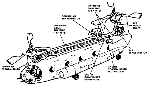
| The drive system delivers torque from the engines to the rotary-wing heads and blades via the forward, combining and aft transmissions. Mounted on the aft transmission are the two 40 kVA AC generators and pumps for the number two flight control hydraulic system and the utility hydraulic system. The aft transmission drives a separate vertical aft rotor shaft. This shaft is splined to the aft rotary-wing head to drive the aft rotor blades. |
|
| The aft transmission receives input torque from the combining transmission through the aft drive shafting. It transmits torque to the aft rotor shaft through a splined connection. | ||
| Spur gears in the transmission provide power to drive pumps for the number two flight control hydraulic system, the utility hydraulic systems, and the two 40 kVA AC generators. | ||
|
||
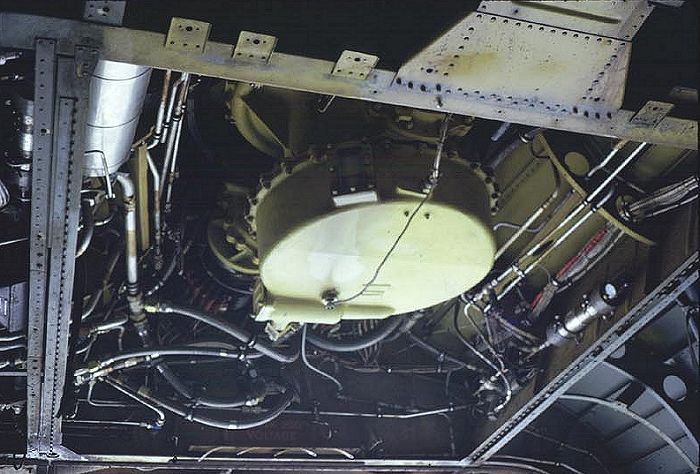
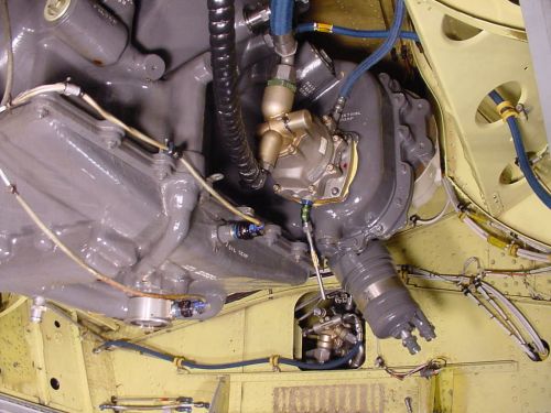
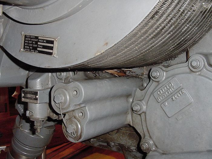
| In the photograph above, the two round white objects are the generators. Near the top center, which is the aft end of the transmission, is the cooling fan. The gray canister near the left lower edge is the aft transmission filter. The view is from the ramp, looking straight up at the transmission. | ||
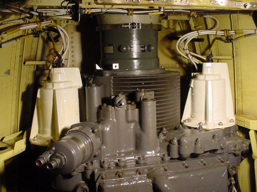
| Looking aft towards the ramp, the next photograph shows the Number Two Flight Boost Pump, mounted on the left side of the transmission. A portion of the Chinook's famous "Bow Tie" is visible on the bulkhead to the aft of the transmission. | ||
|
||
| The transmission is mounted above the ramp area of cabin at the base of the pylon. Access is through hinged baffles and a removable drip tray at the bottom of the transmission. | ||
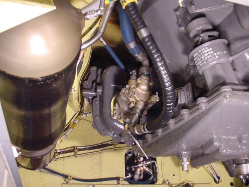
| Shown below is the Utility Hydraulic System Pump, mounted on the right hand side of the Aft Transmission. Also visible is the oil fill port on the right center of the picture, and just aft of it is the oil level sight guage. On the left side of the picture is a large black painted cylindrical container. This is the 375 cubic inch utility system accumulator. It is used for storing hydraulic fluid under pressure that can be used for starting the APU when the main engines are not operating, as well as limited operation of the utility subsystems in the event of a utility system pump failure while in flight. | ||
|
||
| The aft rotor shaft is splined to the top of the aft transmission. It transmits input torque from the transmission to the aft rotary-wing head and rotor blades. The shaft turns in a bearing that is part of a support bolted to the pylon structure. A slider shaft is mounted on the rotor shaft and bolted to the support. It provides the bearing surface for aft swashplate motion. | ||
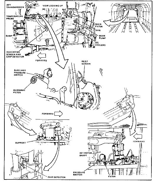
| Hot oil from the aft transmission and rotor shaft passes through a circular oil cooler mounted on the aft end of the transmission. The oil is cooled by a fan that pulls air through the cooler. The fan is driven by the transmission through a splined shaft. Oil is circulated by main and auxiliary pumps. The main pump is at the aft end of the transmission. The auxiliary pump is at the bottom of the transmission, covered by the sump. | ||
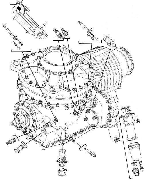
| The lubrication system of the aft transmission is monitored and protected by the following: | ||
| (1) A combined indicating screen and chip detector, and a temperature sensor on the aft transmission sump. | ||
| (2) A chip burn off system that lets the chip detector burn off light fuzz and similar normal debris before it activates indicators on the master caution and maintenance panels. | ||
| (3) An inlet screen inside the aft transmission sump. | ||
| (4) Main and auxiliary pressure switches, a main inlet screen and an auxiliary filter on the left side of the aft transmission. | ||
| (5) A main filter that is located on the aft left of the aft transmission. | ||
| In addition, the condition of oil at the aft rotor shaft bearing is monitored by a chip detector, a pressure switch, and a filter in the shaft support. |
|
|
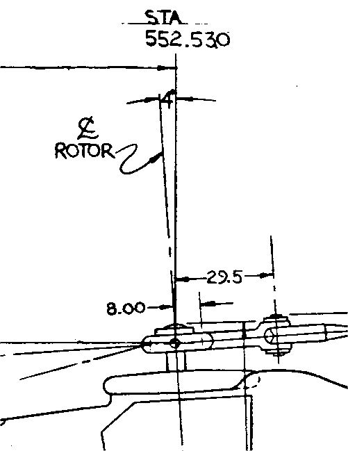
| A Boeing drawing that shows the tilt of the Aft Transmission and Aft Shaft set to 4 degrees forward. |
| Shown below are the Second Stage Planetary Gears in the Forward Transmission that are partly responsible for the August 1999 worldwide grounding of the Chinook fleet. During a transmission overhaul, a 145DS010-8 second stage planet gear/bearing assembly in a British Royal Air Force HC-II (CH-47) was found to contain a crack in the spherical raceway of the gear. Subsequent metallurgical investigation determined the crack to be from a grinding process during the original manufacturing stages which had not been detected during final inspection of the product. Further inspection of other new first and second stage planet gear/bearing assemblies found additional second stage planetary gear/bearing assemblies with similar cracks. The Planetary Gears are the six smaller gears located around the larger Sun Gear in the center of the transmission. |
|
|
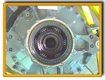
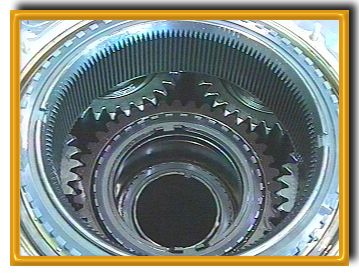
| The Forward and Aft Transmissions of the CH-47D are similar in design and transmit torque from the Combining Transmission to their respective Rotary Wing Head. The torque is transmitted through a Spiral Bevel Ring Gear. At this point, the direction of torque is changed from horizontal to vertical, with the two transmissions driving the rotor system in opposite directions. When viewed from above, the forward rotor system turns counter-clockwise and the aft turns clockwise. The Ring Gear is bolted to the first stage Sun Gear. The Sun Gear, in turn, drives the first stage Planetary Gears which mesh with a Stationary Ring Gear. |
| The non-rotating ring gear causes the Planetary Gears to revolve around the Sun Gear. The Planetary Gears are attached to the first stage carrier which revolves around the Sun Gear. The upper portion of the first stage carrier forms the second stage Sun Gear and it drives the second stage Planetary Gears. These Planetary Gears are attached to the second stage carrier and revolve in the same manner as the first stage Planetary Gears and carrier. |
| The second stage carrier is an integral part of the rotor shaft on the Forward Transmission. On the Aft Transmission, the carrier is splined to receive the Aft Vertical Shaft, as seen in the two photographs above. The second stage carrier on the Forward Transmission and the top of the Aft Vertical Shaft are splined to receive their respective Rotary Wing Heads. |
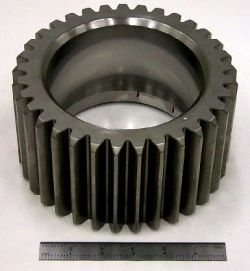
| There are four first stage and six second stage Planetary Gears. The gears are manufactured from a chrome alloy steel. The gears are approximately six inches in diameter. Shown in the photograph to the right is a Second Stage Planetary Gear typical of either the Forward or Aft Transmission. |
|
| The overall speed reduction in the Forward or Aft Transmission is 30.72:1. Given the speed the Synchronizing Shafts are rotating at, 6,912 revolutions per minute (RPM), this drive reduction accounts for the Rotor RPM of 225. |
| The Forward Transmission changes the drive direction 81 degrees. The Aft Transmission changes the drive direction 94 degrees. |
| Aviation Unit Maintenance (AVUM) on either transmission is limited to performing removal and installation, minor seal replacement, cleaning, fluid changes, and other subordinate tasks. |
| Aviation Intermediate Maintenance (AVIM) on either transmission adds the tasks of Sump removal, repair, and installation of Sump related components. Note that observation of the first stage gears only, would be possible with these sumps removed. |
| All other maintenance on the transmissions must be accomplished at Depot, with very few exceptions on a case by case basis requiring specific instructions and approval. |
|
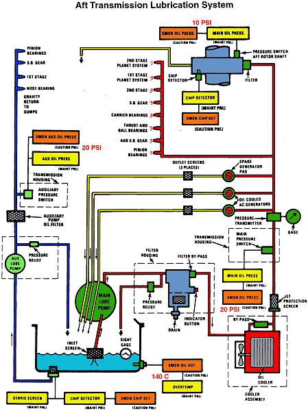
| CH-47D Aft Transmission Lubrication Diagram. Click-N-Go Here to view a larger image. |
|
| On Daily Inspection and Preflight, take a good look at the aft portion of the Aft Transmission abeam the Third Generator Mount Pad and below the Oil Cooler. This area is a favorite spot for b1rds to build nests. It also collects oil, water, grass, and other debris during aircraft operations. If not regularly cleaned, the materials collected will aid the the formation of corrosive substances that eat into the metal alloy used in the construction of the transmission - then you'll replace it. Click-N-Go Here to view a larger image. |
|
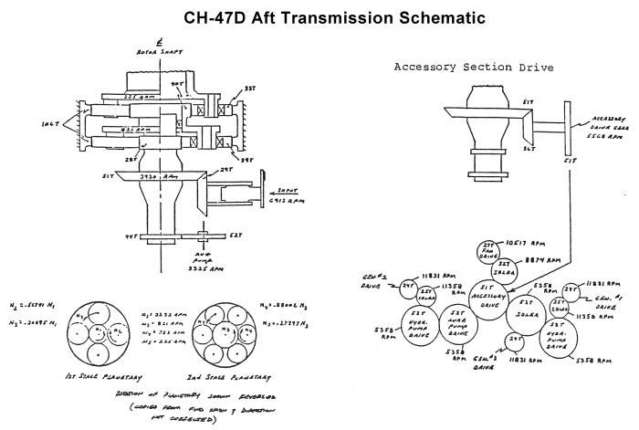
| A drawing showing the internal placement and operation of the gears inside the CH-47D Aft Transmission. Click-N-Go Here to view a larger image. |
|
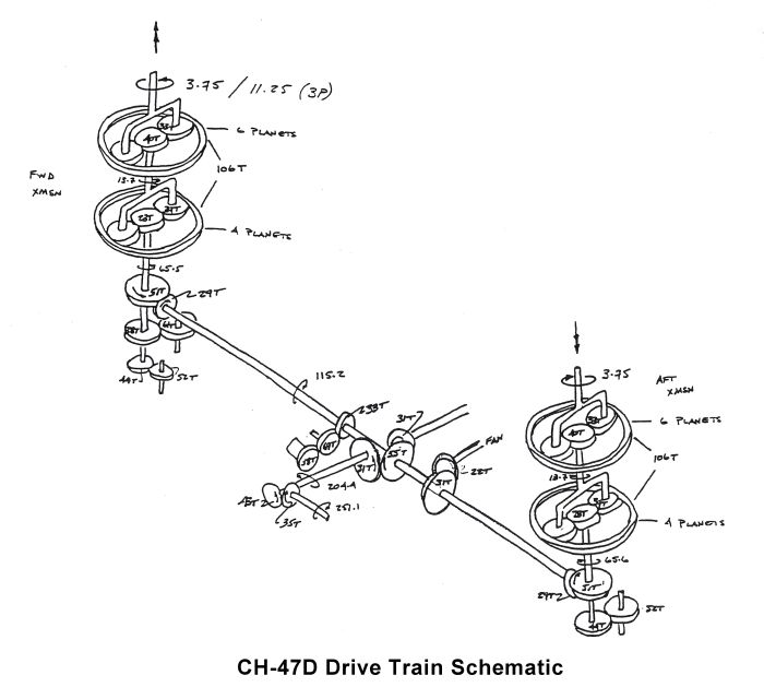
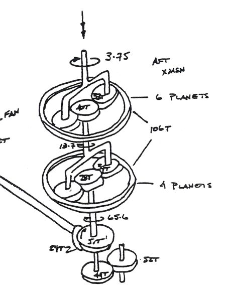
| Above: A drawing showing the placement and operation of the drive shafts connecting the transmissions and the gears inside the various CH-47D transmissions. Upon close examination, one can see that there is not a rigid connection between the input and output of either the forward or aft transmission (see image below). The sun/planetary gear sections (upper portion of the transmissions) rotate around each other. From input to output in each component of the drive train there is large reduction in speed. This translates in to a tremendous increase in torque that is used to drive the rotor system. Numbers associated with a "T" indicate the number of teeth on a particular gear. Numbers associated with a rotational symbol is the speed that component rotates per second. The rotor system rotates at 225 revolutions per minute (RPM). 3.75 blades will pass the same point in space every second. Click-N-Go Here to view a larger image. |
|
| Transmission Classes |
| Click-N-Go on the links below to download some Power Train Study Material. It is recommended you "Right Click" and select "Save As" to download the class to your computer. |
| CH-47 AQC Study Materials |
| Click-N-Go Here to download and study the CH-47 Aircraft Qualification Course (AQC) Power Train Student Handout in .pdf format [3.2 Mb]. |
| CH-47 MTPC Study Materials |
| Click-N-Go Here to download and study the CH-47 Maintenance Test Pilot Course (MTPC) Power Train Student Handout in Microsoft Word format [1.0 Mb]. |
| Click-N-Go Here to download and study the CH-47 Maintenance Test Pilot Course (MTPC) Power Train Powerpoint Presentation [21.7 Mb]. |
| Related Information |
| Honduras Crash |
 |
|
| Comments or Questions ? |  |
Email the Webmaster. |
|
|